


Series DPB
Distributed Power Busway
- 20-30% less expensive than traditional cable/conduit installs
- Finger-safe, indoor rated bus system
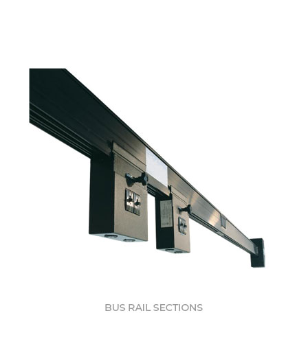
- Multiple Rail lengths:
- 3′, 5′, 6′, 10′, 12′
- 99% Recyclable
- Interchangeable Tap-Off Boxes, 160-400 Amp
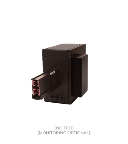
- End Feed/Bus Rail Monitoring, BCM Basic or Plus *optional
- Near-wall mounting okay, due to straight-up Tap-Box install
- Flexible configuration via use of Elbows, Tees, and Cross units
- Options: 150% Neutral ; 100% Rated Isol Ground
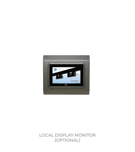
Related Products
Product Description
| Electrical Specs | |
|---|---|
| Bus Ratings (Amps) | 160/225/250, 400,800 |
| Voltage: | 120 thru 600VAC, 3ph 3w or 4w, 100% Neutral |
| Frequency | 60Hz or 50Hz |
| Short Circuit Capacity | 22KAIC @600VAC 35KAIC @480VAC 42KAIC @208VAC |
| Copper Bus Bars Class H (220) insulation |
|
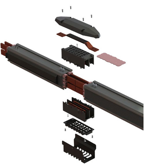
Bus Rail Coupler Technology
- Improved Bus Rail Coupler is 50% less size, and doubled the number of contact points. Minimizes resistance and voltage drop.
- Tested for 60°C ambient (200-400A)
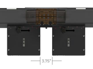
- Compact design minimizes “Keep Out Area”, so more TapOff Boxes can be installed on the rails
- No special tools required for installation.
- Supports BCMS communication cable for secure use of installation & maintenance.
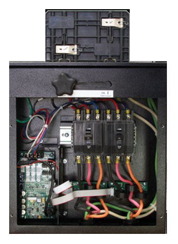
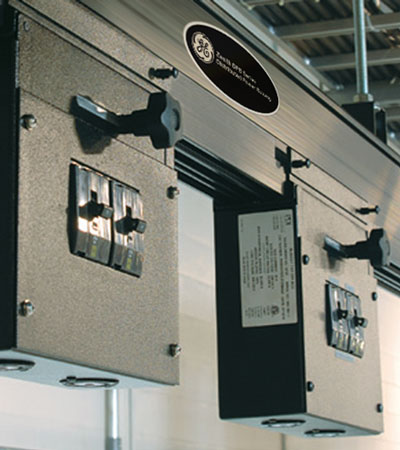
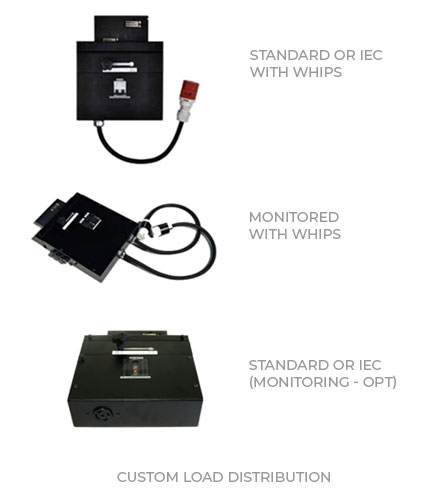
Tap-Off Boxes
- 160-400 Amp
- GE Branch Circuit Breakers, 10 or 22 KAIC
- Multiple Branch Cord Lengths Available
- Multiple Single and Duplex Receptacles/Connectors Available
- IEC/CE Versions Receptacles and Connectors Available
- Branch Circuit Monitoring *optional
Tap-Off Box Connection to Bus Rail
Two Step Process insures Safety and Electrical Integrity

Step 1: Mechanical Connection
- All grounding connections engage & seat directly to the open channel
- Top Mast connects mechanically to the bus rails. Set screws then insure alignment to rails. Rail design prevents backwards installation.
Step 2: Electrical Connection
- Once Top Mast is mechanically secured, the cam action lever seats all electrical contacts against the phase bussing. Once energized, it locks down into position.